13 Common Myths About E‑Bike Batteries, Controllers & Wiring—Busted!
Table of Contents
- Do I Have To Upgrade My Speed Controller When I Upgrade My Battery?
- Amp‑Hour Rating Equals Maximum Current Delivery
- You Should Never Connect Positive to Negative
- Fuses Must Always Go on the “Hot” (Positive) Side
- More Power Runs Through the Positive Wire Than the Negative
- Lead‑Acid Batteries Drain Faster on Concrete
- Conductors Too Close Together Will Spark or Arc
- 48 V × 20 A = 960 W
- Adding Nickel to Copper Conductors Increases Resistance
- Hexagonal or Offset Cell Layouts Are Always More Compact
- Nickel‑Based Battery Packs Are Always Low Quality
- Capacity and Current Carrying Capacity Are Not Linked
- They Say the End Cells Need Double the Connections as Most of the Power Runs Through Them
- Conclusion
Upgrading your e‑bike, electric vehicle, or other battery powered device often raises questions—and plenty of myths—about whether you need to swap out other components, how batteries really behave, and what wiring practices matter. Below, we break down 13 common misconceptions about batteries, controllers, wiring, and pack construction, clarifying each point and adding a bit more detail to help you make informed decisions on your next upgrade.
Do I Have To Upgrade My Speed Controller When I Upgrade My Battery?
There are two reasons why you would need to upgrade your controller after upgrading your battery. A) If your new battery has a higher voltage than your original battery, you will more than likely (but not always) need a new controller to support the higher battery voltage. B) The new battery is the same voltage but supports a higher current level than the maximum current that the controller supports. In that case, you would want a higher current control to take full advantage of the new battery.
A lot of people out there think that if you have a 48 V 10 Ah battery and you upgrade to a 48 V 20 Ah battery, you will have to swap out the controller, motor or other components. This actually is not the case, though.
Remember, the current rating on a battery is simply how much power it can support before overheating and the amp‑hour rating simply indicates how long the battery can deliver current and has nothing to do with the amount of current it can deliver.
Even when your existing controller is electrically compatible, keep an eye on its thermal limits. A battery with higher available energy can sustain high‑current draws longer, so your controller’s heatsink, firmware current‑cut settings, and even your vehicle’s airflow may need reevaluation. In some setups, simply adding active cooling or revising the controller’s current‑limit profile is enough to safely harness the extra capacity without a full controller swap.
Amp‑Hour Rating Equals Maximum Current Delivery
Closely related to the first misconception is the idea that a higher Ah rating somehow forces more current through the load. In fact, the battery will only provide as much current as the load draws. The battery’s maximum current rating (in amps) merely sets an upper limit—it won’t “push” more current into your motor than the controller requests. A higher current capability simply means the battery will run cooler and sag less under load, possibly allowing a bit more sustained power, but it won’t change how much current the motor actually pulls.
When assessing battery performance, also consider C‑rate: the ratio of discharge current to Ah capacity. A battery rated at 2 C can safely deliver twice its Ah rating in amps. So a “bigger” Ah battery built with lower‑C cells might actually have a lower peak discharge capability than a smaller Ah battery built for high‑C output, underscoring why capacity alone doesn’t dictate peak power.
You Should Never Connect Positive to Negative
Under normal circumstances, connecting the positive and negative terminals of a single battery (or power supply) is a short circuit and must be avoided. However, when wiring multiple batteries or power supplies in series—for higher voltage—you do connect the positive of one unit to the negative of the next. That series connection is exactly what creates the increased total voltage.
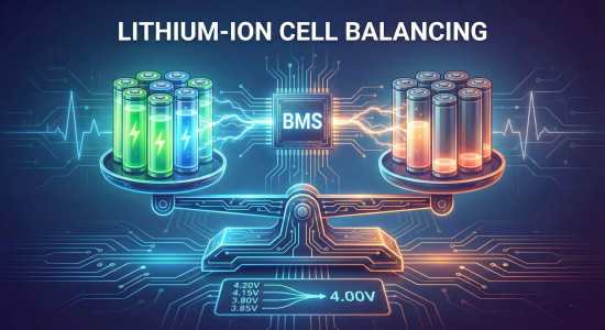
In complex battery arrays—say, a bank of four 12 V lead‑acid batteries wired for 48 V—mixing up series and parallel connections can lead to uneven discharge, cell imbalance, and even thermal runaway. Always double check your configuration: series adds voltages, parallel adds capacities, but never tie positives or negatives across different series strings unless they’re properly balanced with a BMS.
Fuses Must Always Go on the “Hot” (Positive) Side
Because we talk about “hot” (positive) and “ground” (negative), many people insist the fuse must sit on the positive side. In truth, a fuse simply interrupts the circuit, and breaking the circuit on either conductor will stop current flow. Placing a fuse on the negative side is perfectly safe—and often preferable—because if it blows and you handle the fuse holder, you’re touching ground potential rather than the potentially “live” positive side.
In automotive and marine contexts, however, chassis grounds can carry return currents from multiple circuits. Putting the fuse on the negative side in such systems risks blowing unrelated circuits if a return path is inadvertently shared. Always consider the overall grounding scheme before choosing fuse placement.
More Power Runs Through the Positive Wire Than the Negative
Some assume that the positive conductor carries more current or power than the negative (ground) conductor. But it’s a circuit—a closed loop—so the same current flows through every part of that loop. Wherever you break the loop, you interrupt the flow equally.
The only time different conductors might see different currents is in multi‑wire systems with shared grounds or split supplies. For example, in a dual‑supply op‑amp circuit with +15 V and –15 V rails, the ground path may carry the sum of both supplies’ return currents. But in a simple battery‑powered motor circuit, positive and negative wires always match in current.
Lead‑Acid Batteries Drain Faster on Concrete
“Don’t rest your car battery on the concrete floor—it will drain faster!” This old adage stems from the fact that lead‑acid batteries self‑discharge at a noticeable rate, and garages tend to be concrete‑floored. People would set a battery on the ground, come back weeks later, see a lower voltage, and blame the concrete. In reality, it’s the battery’s intrinsic self‑discharge, not the floor material.
Cold temperatures in uninsulated garages can accelerate self‑discharge and plate sulfation in lead‑acid cells. If anything, concrete floors usually stay cooler than wooden shelves, so any voltage drop is more about temperature effects on chemistry than electrical leakage through the slab.
Conductors Too Close Together Will Spark or Arc
Wires or copper traces on a circuit board must be a minimum distance apart, right? Not unless you’re dealing with really high voltages. In air, it takes around 1 kV (1,000 V) per millimeter to create an arc. Since few people are designing thousand‑volt battery packs, the small gaps between low‑voltage conductors won’t spontaneously spark.
Extra detail: That said, in high‑humidity or polluted environments, surface leakage across insulating materials can become significant at much lower voltages. If you’re exposed to salt spray, fuel vapors, or condensation, creepage paths on PCBs or terminal blocks can develop unintended conduction, so maintain cleanliness and appropriate conformal coatings.
48 V × 20 A = 960 W
It’s tempting to multiply battery voltage by maximum controller current to get a theoretical wattage (e.g., 48 V × 20 A = 960 W) and call that the motor’s power. In practice there are significant efficiency losses—in the battery’s internal resistance, wiring, controller electronics, and motor—easily amounting to hundreds of watts. Real‑world power output is always lower than the simple voltage‑times‑current calculation.
Actual delivered power also depends on motor load characteristics and duty cycle. A motor spinning freely under no load might draw only 10 A, while climbing a steep grade could push the controller to its 20 A limit. Monitoring real‑time voltage and current with a wattmeter gives the most accurate picture of system performance under your actual riding conditions.
Adding Nickel to Copper Conductors Increases Resistance
Nickel is added between copper bars and cells in many battery packs, and some believe this reduces resistance. In fact, nickel is far less conductive than copper. The thin nickel foil used for spot welding adds only a tiny incremental resistance along its thickness axis—so small it’s effectively negligible. Across the plane of a busbar (in parallel paths), adding more conductor (nickel or otherwise) will lower overall resistance simply by providing more parallel pathways, but copper is always the superior choice if current is high.
Many high‑end packs combine copper and nickel: copper for the main bus and nickel for intercell welds. This hybrid approach balances weldability and conductivity. If you rely solely on nickel for heavy current paths, you’ll see heat‑related voltage drops under sustained high load, so reserve nickel for spot conduction points and use copper for bulk distribution.
Hexagonal or Offset Cell Layouts Are Always More Compact
A staggered, honeycomb‑style cell layout can pack cells tightly in three or more rows, creating a near‑rectangular envelope. But with only two rows of cells, the offset just produces a wider pack—there’s no real space‑saving benefit. Offset layouts only shine when you have at least three rows to interlock.
Offset layouts also complicate thermal management and wiring. Interlocking cells share heat more uniformly, but routing series leads and BMS taps becomes more intricate. For most DIY packs, simple inline or block arrangements with ample cell‑to‑cell spacing for cooling and easy tap access are more practical.
Nickel‑Based Battery Packs Are Always Low Quality
It’s often said that if your pack uses nickel strips and not pure copper busbars, it must be “cheap” or substandard. While that is probably true most of the time, what actually matters is the amount of conductor and its capacity relative to the load current and pack geometry. A well‑designed nickel strip pack (with multiple parallel layers or sufficiently wide strips) can perform just as well as copper—especially at modest currents or with cells in parallel to share the load. Quality depends on conductor sizing and layout, not the metal’s name alone.
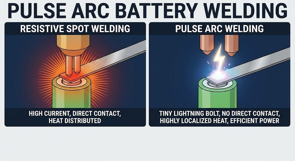
The reliability of a nickel‑based pack also hinges on weld integrity. Poor spot welds, inconsistent weld depth, or insufficient dwell time can create high‑resistance joints. If you choose nickel strips, invest in a quality spot welder and follow best practices for weld parameters to ensure each connection carries full rated current.
Capacity and Current Carrying Capacity Are Not Linked
You hear this all the time. “I have a 48 V 20 Ah battery, and I just upgraded to a 48 V 30 Ah battery, it should be able to handle 50% more current, right? Wrong. This only happens to be the case if the batteries are, in all other ways, equal. So, that means battery A is a 13S4P made with 5 Ah cells and battery B is a 13S6P made with the same 5 Ah cells. In a situation like that, that theory is true because the higher capacity has 50% more of the same type of cells, so yes, as long as the BMS supports it, the battery would have 50% more current carrying capacity than battery A.
The problem is, this is rarely ever the case. More often than not, two mismatched batteries are also mismatched in other ways. Meaning that they have different cells, and the layout and series conductors are more than likely totally different. In this much more common scenario, the load current would be disproportionately distributed between the two mismatched batteries. This is something to account for when putting lithium ion batteries in parallel.
When paralleling entire battery packs, always match their internal impedance as closely as possible. Even small differences in cell chemistry or conductor thickness can cause one pack to shoulder more load, leading to accelerated wear. Using a professional‑grade parallel balancing board or individual cell monitors helps prevent one pack from “hogging” current and ensures uniform aging.
They Say the End Cells Need Double the Connections as Most of the Power Runs Through Them
Some builders believe that the cells at the ends of a series string bear more current than the middle ones and thus require extra tabs. In reality, current flows equally through every cell in a series string—each cell experiences the same amp flow. However, using copper or thicker tabs on end cells can reduce resistance marginally in the interconnects and balance mechanical stresses.
If you do choose thicker end‑cell connections, ensure that the added mechanical rigidity doesn’t warp cell casings or stress the weld joints. A flexible mechanical support or silicone potting can absorb vibrations and thermal expansion, preserving integrity across all tabs—end or middle.
Conclusion
Understanding how batteries, controllers, wiring, and pack layouts interact is key to safe, efficient upgrades. Most myths stem from oversimplified thinking—like equating amp‑hours to peak current or overemphasizing tab placement. By focusing on real parameters (voltage compatibility, current ratings, conductor sizing, and thermal management) rather than hearsay, you’ll get the performance you expect without unnecessary component swaps or wiring headaches.
Always verify specs, follow best practices for connections and fusing, and consider cell chemistry and layout as a whole system. With those fundamentals in mind, you can confidently optimize your powertrain for range, efficiency, and longevity.
We hope this article helped clear up any battery misconceptions you may have had. Thanks for reading!


