Table of Contents
When connecting a battery to a load with a capacitive input, there is a surge of current as the load capacitance is charged to the battery voltage. This inrush current can reach its maximum easily, especially with large batteries and powerful loads, and can peak at 1000A. To prevent this, a precharge circuit is utilized to restrict the inrush current while still allowing the operating current to flow freely.
In some situations not having a pre-charge circuit can be dangerous. In other situations, such as ebikes, having a pre-charge circuit means avoiding an unsettling pop when you go to plug in your controller to your battery. The problem with building a pre-charge circuit is that it is an extremely complicated process that requires a high level of understanding in both math and electronics.
The good news is that if you want to avoid that, all you have to do is get some anti-spark connectors. Anti-spark connectors have a tiny pre-charge circuit built right in so you can incorporate them easily into your next battery pack build. You can use them to easily build inline pre-charge circuit modules. If you don’t want to do any soldering, you can even get an anti-spark cable and put it in series with your normal wiring.
In this article, we will cover what a pre-charge circuit is and how the circuit works so that you can build one if you want to. We will also key you in on some super convenient connectors and adapters that make integrating a pre-charge circuit into your application a breeze.
Reasons for a Precharge Circuit
A precharge circuit is required between a battery and its load if one or more of the following conditions exist:
- The input capacitors on the load could be damaged by the high inrush current.
- The main fuse may fail if it is required to handle the high inrush current.
- Contactors, if present, could be damaged by the high inrush current.
- The battery cells are not designed to handle the high inrush current.
How to Build a Pre-Charge Circuit
The precharge circuit consists of a minimum of two components: a precharge resistor to regulate the inrush current, and a contactor (or high-power relay) that bypasses the resistor during normal operation. Optionally, a precharge circuit may also include a precharge relay that prevents the load from receiving power through the precharge resistor when the system is turned off.
A lot of the time when examining common pre-charge circuits you will find a contactor placed in line with the other end of the battery to isolate the load when the system is turned off. The typical precharge circuit has the precharge resistor on the positive terminal of the battery, but it could also be on the negative terminal.

Operation
In its most basic form, the precharge circuit operates as follows:
- Off: All relays/contactors are off when the system is off
- Precharge: When the system is first turned on, K1 and K3 are turned on to precharge the load until the inrush current has subsided
- On: After precharge, contactor K2 is turned on (relay K1 may be turned off to save coil power)

Pre-Charge Circuit Part Selection
Contactors
In a well-designed system, under normal operation, the contactors are not required to interrupt the operating current, so only the carrying current rating needs to be sufficient for the average load current. For example, a contactor with a 50A breaking current rating and a 100A carrying current rating will work with a load that draws 100A average.
The contactors must be rated for the maximum battery voltage, as that voltage will be across the contacts when they are opened. Additionally, they must be rated for DC operation.
Precharge Relay
The precharge relay needs to be rated for the full battery voltage because the full battery voltage appears across its contacts when the system is off. An AC relay may be used because by the time it's turned off, the current through it has gone to 0A.
Resistor
The selection of the precharge resistor is based on the load capacity and the desired precharge duration. The precharge surge current reduces to 1/e of its initial value after a time of R * C, where R is the resistance and C is the load capacity. To reach a manageable current value, approximately 5 * T (5 times the time calculated above) is needed.
For example, if the desired precharge time is 500 ms and the load capacity is 10,000 µF, the resistance would be 10 Ohms (calculated as 500 ms / 10,000 µF / 5).
The precharge resistor must be able to dissipate the same amount of energy stored in the input capacitors of the load. For instance, if the battery voltage is 100 V and the capacitance is 10,000 µF, the energy stored in the charged capacitors would be 50 Joules and is calculated like this:
(10,000 µF x 100 V^2) ÷ 2 = 50 Joules
The power dissipated by the resistor during precharge is calculated as the energy divided by the precharge time, e.g. 100 W for a precharge time of 500 ms (50 J / 500 ms). At the start of the precharge, the instantaneous power will be quite high, for example 1000 W for the example above (calculated as 100 ^2 / 10).
But if you think about it, the precharge resistor will not need to dissipate any significant power for a long period of time. During the precharge, the resistor will be stressed by the high, sudden power, just for a split second.
You can overcurrent a pre-charge resistor to a pretty significant degree and not have any problems. For example, a particular resistor might be rated for 50 Watts but its spec sheet states something like, ‘Overload: 5 times rated wattage for 2 seconds.’ This means that the 50W resistor would be able to handle 250W for 2 seconds, which is far longer than any precharge would be.
As you can see, building your own pre-charge circuit is a super complicated endeavor. Luckily, there is a much easier way.
Connectors With Built In Pre-Charge Circuits
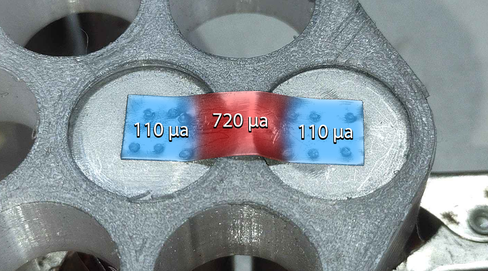
Anti-spark connectors are designed to prevent high-voltage sparks when connecting or disconnecting a battery from an electrical device. These connectors have a built-in precharge circuit that helps to regulate the inrush current and prevent damage to the electrical components. The precharge circuit in an anti-spark connector consists of a resistor that limits the initial surge of current that occurs when the battery is first connected.
The anti-spark connector works by slowly ramping up the voltage to the load, allowing the input capacitors to charge gradually and reducing the likelihood of a high-voltage spark. The precharge resistor restricts the initial surge of current, preventing the high inrush current from damaging the electrical components or causing a spark. Additionally, the anti-spark connector includes a relay or contactor that bypasses the precharge resistor during normal operation, allowing the full battery voltage to be applied to the load.
Overall, the built-in precharge circuit in an anti-spark connector offers several benefits, including protection against high voltage sparks, reduced likelihood of damage to the electrical components, and improved safety. By limiting the inrush current and gradually ramping up the voltage to the load, anti-spark connectors help ensure a safe and reliable connection between the battery and the electrical device.
The easiest way to add a pre-charge circuit to just about any application is to use an anti-spark connector. One of those cables is just about the easiest way to add a pre-charge circuit. You can easily make your own in-line pre-charge circuit adapter by taking an anti-spark XT90 female connector and mating it to any XT90 male connector. This can either be done directly, back-to-back with solder or you can make a short cable adapter.
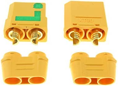 Anti-Spark XT90
Rated current 90A and a very simple way to avoid the pop when attaching a battery to the load.
Check Price
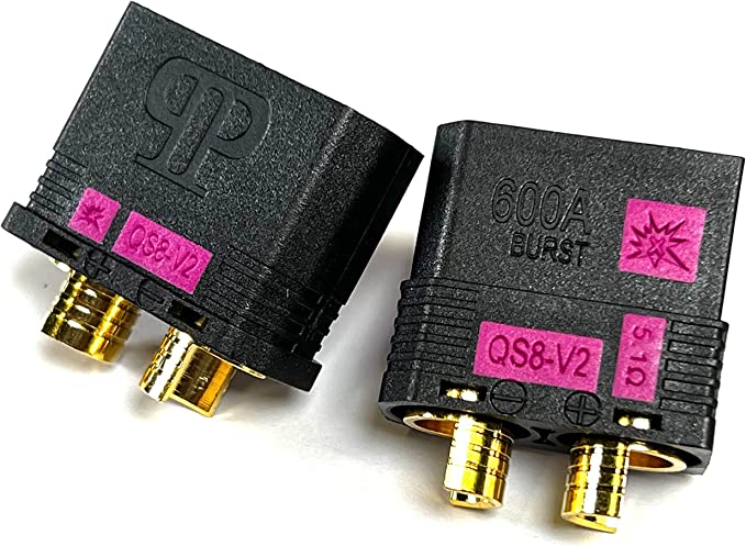 Anti-Spark QS8 V2
High current 600A and a very simple way to avoid the pop when attaching a battery to the load.
Check Price
Conclusion
When connecting a battery to a load with capacitive input, a surge of current occurs as the load capacitance charges to the battery voltage. This inrush current can easily reach its peak, especially with large batteries and powerful loads, and can reach 1000A or more! To avoid this, you can use a precharge circuit to limit the inrush current while still allowing the operating current to flow smoothly.
In some cases, not having a precharge circuit can be hazardous. In most other cases, a precharge circuit simply exists to prevent an unpleasant pop when connecting the controller to the battery. A precharge circuit is relatively inexpensive to produce, but designing a precharge circuit is a complex process that requires a lot of pre-developed skills.
An easier solution is to use anti-spark connectors, which have a built-in precharge circuit. These connectors can be used to build inline precharge circuit modules without soldering. Alternatively, an anti-spark cable can be used in series with the normal wiring to achieve the same result without any soldering.
We hope this article helped you learn everything you needed to know about precharge circuits. Thanks for reading!!
Turn the guide into a real build plan
If this article is part of an actual battery, powerwall, or pack-design project, the next step is usually moving from theory into the calculators and planning tools.
Personal Electric Vehicles
If this article sent you down a deeper rabbit hole, the topic page collects the rest of our guides, explainers, and project notes in this category.
Browse Personal Electric Vehicles