Battery balancing keeps cells at the same state of charge so no one cell charges too high or discharges too low. When cells go out of balance, the BMS cuts off the whole pack early — protecting the weakest cell but leaving capacity on the table. Here's how balancing works and what to do about it.
Why cells go out of balance
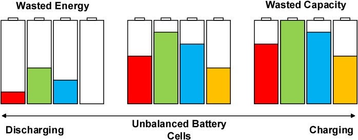
No two cells are identical. Slight differences in capacity, internal resistance, and self-discharge rate mean cells at the same starting voltage will drift apart over time. Cells with slightly lower capacity reach full charge first and hit the high-voltage cutoff before the rest. The BMS then stops charging the whole pack, even though most cells still have room. Over dozens of cycles, this drift compounds.
Series packs drift more noticeably than parallel packs because each group's voltage is monitored individually. A parallel group averages out differences between cells in that group.
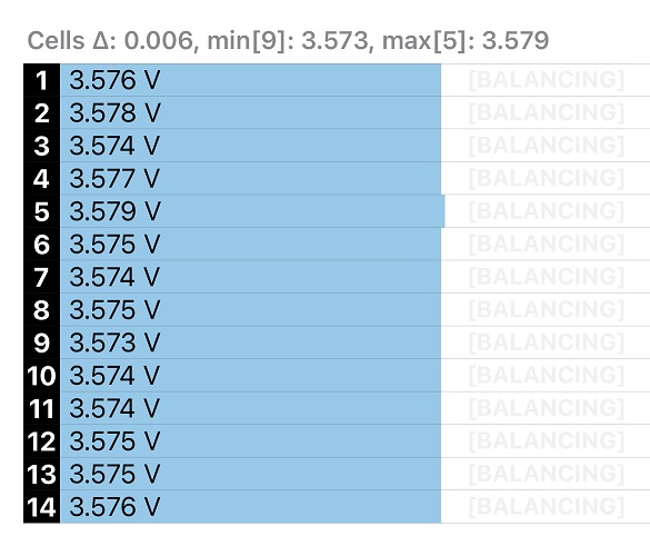
Balancing in series packs
In a series pack, each group of parallel cells forms one "cell" from the BMS's perspective. The BMS monitors the voltage of each group and balances by bleeding charge off the highest-voltage group.
Passive balancing
Passive balancing dissipates excess charge as heat through a resistor on the high cell. The BMS activates the bypass resistor on any cell that exceeds a set threshold (usually within 10 to 20 mV of the pack maximum). The current through the resistor is the balance current — typically 50 to 300 mA for BMS units.
Passive balancing only works at the top of charge. The BMS can only bleed off charge from high cells while the pack is near full — it can't push charge into low cells. This means balancing happens during the final stage of charging, when all cells are approaching full.
Active balancing
Active balancing moves charge from high cells to low cells using inductors, capacitors, or transformer-based circuits. It's more efficient than passive (no charge wasted as heat) and works throughout the charge/discharge cycle, not just at the top.
The tradeoff is cost and complexity. Active balancing BMS units like the JK BMS cost more than passive units but are worth it for large packs (100Ah+ per cell) where a small state-of-charge difference represents significant capacity.
Balancing in parallel packs
Cells in parallel self-balance through direct electrical connection — current flows between cells until their voltages equalize. This happens automatically and continuously. A healthy parallel group has all cells at the same voltage all the time.
Where parallel packs run into trouble:
- Mismatched capacity: Lower-capacity cells in a parallel group reach full charge first and can block the group from accepting more charge, reducing the effective group capacity.
- Mismatched IR: High-IR cells take less of the current during charge and discharge, effectively reducing their contribution. Over time, this means the low-IR cells do more work and degrade faster.
- Connecting cells at different voltages: When paralleling cells, always equalize them to within 0.05V of each other first. Connecting a 4.2V cell to a 3.5V cell creates a large current surge through the cells and wire, potentially damaging both.
When you need a standalone balancer
Most BMS units include passive balancing. If your pack is balancing correctly through the BMS and cells stay within 20 to 50 mV of each other after a full charge cycle, you don't need anything else.
You might need a standalone balancer if:
- Your BMS has no balancing function (bare protection boards for some low-end packs)
- Your cells have significant capacity mismatch that passive balancing can't keep up with
- You're running a large LFP pack that stays at partial SoC most of the time (passive BMS balancing only works near full charge)
- You want to balance a pack without running it through a full charge cycle each time
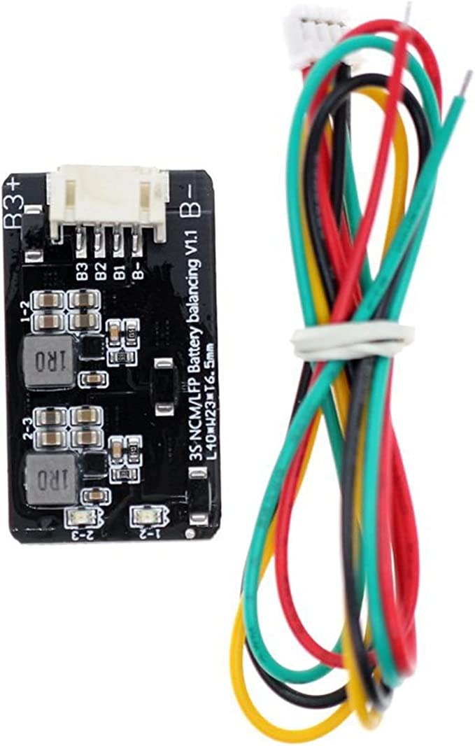
Standalone active balancers (like the Heltec active balancer units) connect in parallel with each cell group and continuously move charge from high cells to low cells. They work at any SoC, not just at the top of charge.
How to manually balance a drifted pack
If your pack has drifted badly and the BMS keeps cutting off early, you can manually top-balance: charge each cell group individually to the same voltage (4.20V for NMC, 3.65V for LFP) before reassembling the series string. This brings all groups to the same state of charge and gives the BMS a clean baseline to work from.
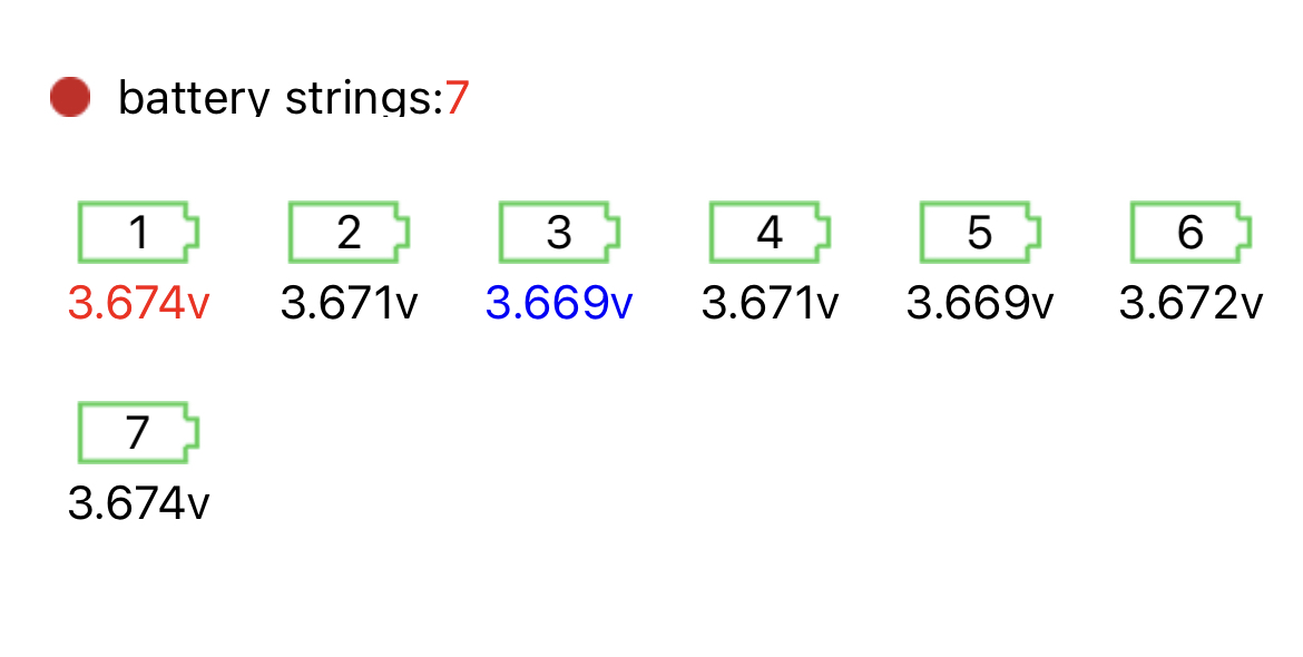
Top balancing is a one-time reset. After that, the BMS passive balancing should maintain the balance from cycle to cycle.
How long does balancing take
With a 100 mA passive balance current, a cell group that's 500 mAh out of balance takes 5 hours to balance. With a 1A active balancer, it takes 30 minutes. For a 280Ah LFP cell that's 1Ah out of balance, a 100 mA passive balancer needs 10 hours. A 2A active balancer handles it in 30 minutes.
This is why larger packs benefit more from active balancing — the time savings are significant, and passive balancing may never fully converge if the cells are cycling faster than the BMS can balance them.
Wiring LiFePO4 Battery Banks In Parallel: Two Methods
There's two ways to wire batteries in parallel. You can do a simple daisy chain setup where one battery connects to the next battery in a row, and at one end of the row you'll have your positive and negative connections for energy to go in and out of the battery bank.
Or you can do a star topology where all the batteries have the same length cables and connect to some central point.
The Daisy Chain Arrangement
The first one we'll cover is the daisy chain arrangement. This can work fine in many applications as long as you consider:
- the amount of current that you're going to draw,
- the amount of current that each battery can support, and
- the amount of current that your parallel connections can take.
For example, if you have three 100 amp hour LiFePO4 batteries wired in parallel and they can each do 200 amps of current, that means the battery bank as a whole can do 600 amps of current.
Your series connections are extremely important when you're wiring LiFePO4 battery banks in parallel. If the cables can only do 200 amps each and you put a 600 amp load on the battery, in an ideal world each battery would see 200 amps of the load because it would be split three ways.
But remember they're all connected with the same 200 amp cable, and the electrons will take the path of least resistance. So if you have one long cable that's the same width the whole way down, the further and further you go, the higher and higher the resistance.
That means even if all of your LiFePO4 battery banks have the same resistance and they can all handle a very high current, if you have them in a daisy chain and you draw a high current from them, the battery closest to the terminals, the output, will see most of the load.
It will be somewhat split amongst the batteries, but most of the load will be seen by that first battery. Its voltage will drop more than the batteries at the end because the batteries at the end are seeing a much lighter load.
The LiFePO4 voltage chart shows how discharge current changes measured voltage and lets you compare cell, 12V, 24V and 48V references. A voltage reading on its own does not give an exact charge percentage.
And then in an instant, right then and there, the batteries at the end will be charging the batteries closer to the terminals. This happens very quickly and ultimately isn't dangerous, but it does reduce the life of the batteries.
Improving the Daisy Chain Setup
The best way to wire LiFePO4 battery banks in parallel, if you're going to do the daisy chain method, would be to use more and more cable to connect each battery further and further down the line.
So you might use one positive and one negative cable for the first two batteries. And then for the next two batteries, you can use two positive and two negative cables. And then for the next two batteries, use four positive and four negative cables.
That way, you don't have to use so many cables the whole way down, and doing this will help even out the resistance.
If you don't want to do all that, then just make sure to keep your load at about half of your total current. So if you can support 600 amps, do 300 amps on the battery bank and it'll be just fine. But it will have a slightly reduced life because of that.
The Star Topology Arrangement
The other way is by organizing them in a star topology. If you have all of your batteries surrounding an area where you want to put your terminals, you can simply use the same length cable to connect all of those batteries to that common terminal. This will make a circular-shaped setup, but it makes it extremely easy to get balancing just right.
You could obviously arrange the batteries any way you want and just make sure you use the same length cable for each battery. But you'll end up with a bundle of cables somewhere or in multiple places if you do that, which is why I suggested the radial arrangement for connecting LiFePO4 battery banks in parallel while maintaining the balance of the parallel connections.
FAQ
- How often should I balance my battery pack?
- A BMS with balancing enabled balances continuously (passive) or whenever needed (active). You shouldn't need to manually balance a healthy pack with a functioning BMS. If you're manually top-balancing regularly, something is wrong — either the BMS balance current is too low for your pack size, or cells are mismatched and need replacement.
- Can I parallel two packs with different states of charge?
- No — not directly. Large voltage differences between packs cause a current surge when connected. Always charge both packs to the same voltage first, then connect them through a battery combiner or charge controller that manages the connection safely.
- Why does my BMS show cells drifting even though I just balanced them?
- Probably cell capacity mismatch. If one group has lower capacity than the others, it will reach full charge faster on the next cycle and appear to drift again. The fix is replacing the low-capacity group with matched cells, not re-balancing repeatedly.
- Does balancing work differently for LFP vs NMC?
- The mechanism is the same, but LFP's flat voltage plateau makes early voltage-based balancing less effective. LFP cells at the same voltage can have quite different SoC. This is why active balancing or top-balance initialization is more important for LFP packs than NMC packs.