Table of Contents
Structured from the original text with only basic corrections (typos/units). Charts are generated from the logged readings.
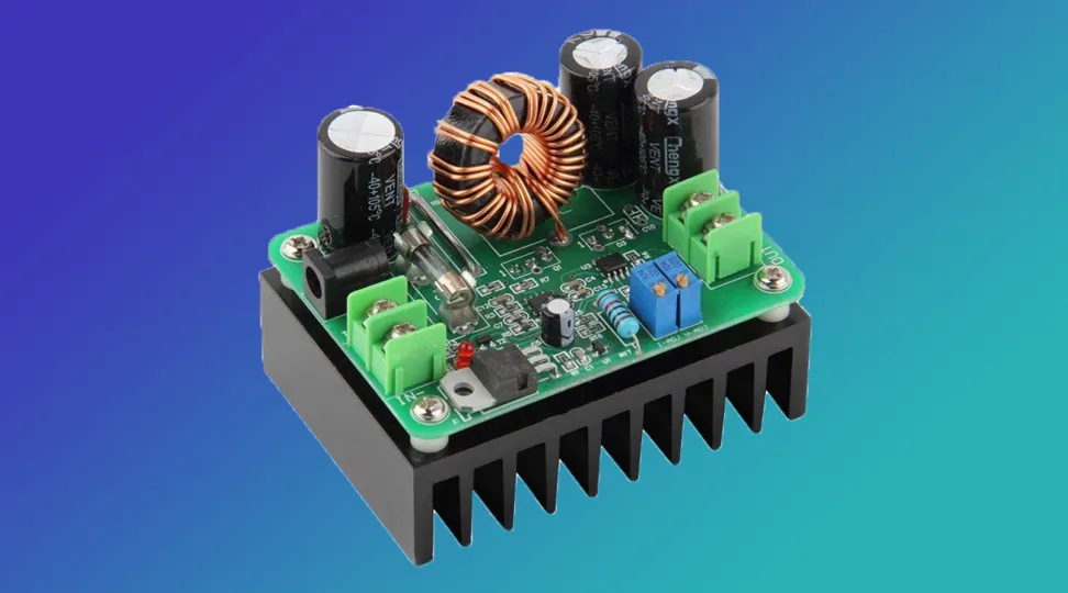
I found a compact, small footprint, 600 watt, high power, DC-to-DC boost converter on Amazon, so I figured I would order it to try it out.
Spec Sheet (as listed / as observed)
Item | Value
Product type | DC-to-DC boost converter, constant-current (CC) / constant-voltage (CV)
Claimed power rating | 600 W (listing)
Input voltage range (listing) | 12–60 V
Output voltage range (listing) | 12–80 V
Controls | Current control knob + voltage control knob
Inputs | Screw terminal pair + DC barrel jack (also useful as a fan power connector)
Dimensions (measured) | ≈85 × 62 mm footprint
Height (measured) | ≈70 mm tall (stacked on its own heatsink)
Price (as purchased) | $18.99 on Amazon (free shipping at time of purchase)
Listing notes on current/power | Mentions up to 15 A input current; also describes “effective power” as input voltage × 10 A
Observed behavior | Struggles near/below 12 V input at high load without forced air; cannot regulate current down to 0 A (has a minimum current that drifts)
Hardware notes | Fuse runs hot; blown fuse under surge during battery charge test; connectors feel loose
Why I Bought It
It has a 12 to 60 volt input range and a 12 to 80 volt output range. It's a constant current boost converter, so that means that you have a current control and a voltage control knob.
Doing the Rating Math (and Why the Listing Is Confusing)
It says it's a 600 watt board, but let's do some math real quick. It doesn't say how many amps it supports, and it doesn't specify whether they mean 600 watts on the input or the output.
We can assume output, and we can kind of infer the amps, I guess. 600 watts divided by 12 volts, which is the lowest the output goes, that's 50 amps. I can tell you right now, even with a massive fan, this board's not going to support 50 amps without melting.
So let's try the other end of the voltage, 80 volts. 600 divided by 80. 7.5. Now that's more reasonable, but at what input voltage? Because the difference between input and output voltage makes a difference in the converter's efficiency. It's not directly proportional, as it would be for a linear regulator, but it still is a large part of the equation.
If it is 7.5 amps at 80 volts to make the 600 watts, then what's the input voltage? Is the input voltage 12 volts? Well, 600 divided by 12 would be 50 amps. Like I said, this board's not going to be able to handle 50 amps, just based on the size, the connectors, and all of that.
So let's give it best case scenario, 60 volt input. That's 600 watts divided by 60 volts. And then we have 10, a nice solid figure.
So it looks like this board is rated for 10 amps of input current and 7.5 amps of output current.
But then at the bottom of the page in the product description, it says that it supports an input current of up to 15 amps. Okay? So if it can support an input current of up to 15 amps and it has a 600 watt limit, that's 600 divided by 15. So that's assuming a 40 volt input.
So you can see how it's not really clear how much power this can do. They do explain the output power in this way, though. They say the effective power is the input voltage times 10 amps. Now that sounds interesting because they said it has a 15 amp current limit. So does the regulator consume 5 amps when in that condition? No. So it's just not very obvious how much current this is claimed to be able to handle.
Physical Design Notes
Before we get to the tests, I would like to talk about a few properties of this regulator.
Compact footprint
Number one, it has a very small footprint. It is stacked on its own heatsink, so it sits flat very nicely, and it doesn't take up much space. It's just 85 by 62 millimeters, give or take a millimeter or so of tolerance. And it's 70 millimeters tall. So it is rather thick compared to its XY dimensions, but it is still very compact.
Two inputs (and why the barrel jack is useful anyway)
It has two inputs, one being a screw terminal pair and another being a standard DC barrel jack. Now I don't use DC barrel jacks that much because, you know, they're kind of difficult to work with. And they're not exactly standard sized. And they're pretty high resistance. So I generally would just ignore that port.
But because this can do high power, it's going to get hot. So that secondary input can be used as a fan power connector. And it works really effectively like that.
Fan voltage
And the ideal fan voltage to use would be a 24-volt fan. Because, you know, this being a boost converter, the input voltage is always going to be lower than the output voltage. And although it does support a higher than 24-volt input voltage, if you had a 24-volt fan, you'd be able to safely run this module at up to around 35 volts or so, or something like that.
And while running it at 12 volts or 15 volts or whatever, the 24-volt fan would be spinning slower. But at the same time, it doesn't take much air to cool off, you know, a big, nice heatsink like this with lots of fins. So it would probably work fine.
What I used
In my testing, I've used a 12-volt fan. The 12-volt fan can last briefly or even for surprisingly extended periods of time at 15, 18, or 24 volts.
There are several situations where you can run this module without a fan. But there's also several other situations that you'll definitely need a fan. We'll get to those in a moment.
Pros and cons (quick)
The small footprint and the auxiliary power connector are pretty much the only pros other than the price. This regulator is cheap. It's only $18.99. Free shipping on Amazon.com.
Test 1: Running Below 12 V Input (High Load)
It says it has a 12-volt input voltage, so I wanted to run it under that to see how it performed. And I took five readings evenly spaced over the course of 15 minutes.
In my first reading, the input voltage was 11.8 volts. And the output was set to 29.4 volts. But with the 9.1 amp load, which was a piece of nichrome wire cooled by a fan, it was not able to maintain voltage boost all the way to the set amount, and it only made it to 26.3 volts.
On my next reading, the input voltage had fallen to 11.3 volts, and the output voltage was 25.2 volts, and the current had fallen to 8.8 amps because it's a constant resistance load. So as the voltage drops, the current is also going to drop.
In my next reading, it was 11.1 volts on the input, and the output had fallen to 24.9 volts. It's having an even harder time regulating the voltage. And as a result, the current had fallen to 8.64 amps.
Then on my next reading, voltage had fallen to 10.78 volts, causing the output voltage to fall to 24.6 volts, with a resulting output current of 8.59 amps.
Then on my next reading, the input voltage had fallen to 10.57 volts, and the output voltage had fallen to 24.4 volts, resulting in an output current of 8.48 amps.
I checked the temperature about three-quarters of the way through the test, and I saw that the heatsink was at about 60 °C, and the top of the board where the inductor and capacitors are was at 170 °C. And believe it or not, it survived. It was still running. It was probably going to burn up at any moment, but at that moment, I plugged in the fan, and then everything went well for the rest of the test.
So in that test, we could see that as the voltage dropped on the input, it was harder and harder for it to maintain the set output voltage, which resulted in rapidly increasing temperatures and an inability to maintain a consistent output current, despite the fact that the output load resistance is consistent.
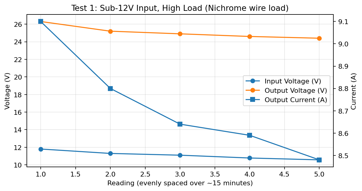
Test 1 chart: input voltage droop vs. output voltage and output current (five evenly spaced readings).
Test 2: Charging a 7S NMC Battery (Minimum-Current Behavior)
And then I did another test that had a higher input voltage, and in this test, I'm using the regulator to charge a 7S NMC lithium-ion battery. I have the output voltage set to 29.4 volts, and the battery is at around 23.5 volts, or something like that.
I have the current set all the way to zero. I turned the current knob counterclockwise until it started to click, meaning that it is absolutely at the end of its range. And even still, when I plugged it in, the output voltage went to 24.2 volts, and there was 1.96 amps of current flowing.
I saw a 1.5 amp minimum current in a similar recent test that I did. So I would say that this regulator cannot regulate current down to zero.
No boost converter can regulate voltage down to zero, because it can only increase voltage. It cannot decrease voltage. But this particular boost converter cannot even regulate current down to zero.
It should be able to, because if the set output voltage is higher, you know, much higher than the input voltage, so you have a lot of range, and you set the current to, say, one amp or two amps or whatever, the boost converter should be able to regulate the voltage to the point to where it is however many volts over the battery you connect it to to produce that many amps.
So if you set it to zero, then it should be able to set its voltage to the battery voltage, right at the battery voltage, so that no current flows. Well, this regulator cannot do that.
And in my very first reading, we're getting almost two amps. Luckily, the battery I'm charging with it can support that. It's a 4P battery using 18650 cells, LGMH1 to be specific.
On my next reading, the input voltage had fallen to 13.44 volts, and the output voltage had risen, as you'd expect, because it is set much higher than that, and it is charging the battery. But the output current fell from 1.96 amps to 1.88 amps.
So this is showing that this regulator is having a hard time regulating the bottom end, even when you give it greater than 12 volts.
On my next reading, the input voltage had fallen to 13.07 volts, and the output voltage had risen again to 24.4 volts, but the current yet again fell, and it was now at 1.78 amps.
On my next reading, the input voltage had fallen to 12.38 volts, the output voltage had risen to 24.7 volts, and the current was at 2.97 amps, and that's because I had turned it up until it got to 3 and stopped.
So before, I had it set to absolute minimum, and we were getting this random minimum current that was changing with the input and output voltage as they changed. But then I turned it up to where it was solid 3.
So then on my next reading, input voltage dropped to 11.82 volts below the 12-volt minimum, and it was no longer able to regulate the 3 amps that I set. The output voltage had still risen to 24.8 volts, but current had fallen to 2 amps.
During the entire time of this second test, the fan was not on, and the temperature rose from 34 to 35 °C for the heatsink and from 37 to 39.6 °C for the top of the board where the inductor and capacitor are.
This test went pretty well. It was stable. It didn't do anything that would harm the battery, but it has a minimum unpredictable current that somewhat drifts as the battery voltage changes.
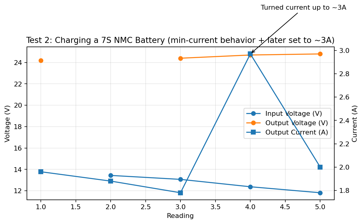
Test 2 chart: readings from the battery-charge test (gaps indicate measurements that weren’t stated in the notes).
Test 3: “Ideal Conditions” Regulation Check (23 V Input)
So I want to do another test to see if it can regulate at all to try to give it more ideal conditions. And I did. I gave it 23 volts at the input from a 7S battery that was pretty low. And I set the current to 5.13 amps, and I connected it to a constant resistance load.
And sure enough, for the duration, it maintained a 29.2 volt output and 5.13 amps of current the entire time, with the heatsink rising from 35 °C to 47 °C and the top of the board rising from 38 to 62 without a fan.
If you plug a fan in, you can get a whole lot more current from this thing.
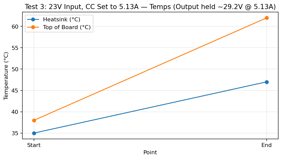
Test 3 chart: temperature rise while holding ~29.2 V at 5.13 A.
Other Issues / Notes
So yes, it's compact and has two inputs and low cost, but there's a few things about this board. It has that weird minimum current. It cannot regulate to zero amps.
Oh, and there's no easy way to mount the fan. Because of how everything's designed, you know, you would usually mount the fan on the heatsink, but because this is designed to sit flat on the heatsink with the controls and everything facing up, there's no easy way to mount the fan.
You have to make some sort of jig or container or 3D print something or carve something out of wood or something. You have to rig something up or design something in order to cool this outside of leaning a fan against it, which is not ideal.
Also, it has a weak fuse. Even when operating it at just a few amps within its normal input range, and output range, I could notice the fuse was getting very, very hot. And then when I set it to 5 amps and then plugged the battery in, the surge current from charging that battery from a 12 volt input blew the fuse.
So what I did is I just soldered a wire over it. I'm not recommending doing that. I did that because I wanted to see what the regulator itself could handle. I'm using this regulator in a controlled fashion on a bench, a proper workbench, connected with things that have protection circuits of their own or fuses of their own. So I'm not bypassing the fuse out of a disrespect for caution or what could happen. I'm bypassing the fuse so we can see what the regulator itself is capable of without this fuse getting really hot.
But the proper solution would be to replace this fuse with a larger fuse or just a higher quality fuse. And also you might want to bend the connectors inward a little bit because it's just too loose. That may have been part of the problem in the first place.
Recommendation
Here's the big question. Do I recommend buying it? Absolutely.
If it was $30, I would say no. Or if it was more unstable, I would say no. Or if it was the same price and had exactly the same exact performance as it currently does, but it was three times larger, I would say no.
But because this is compact, has this nice little cube form factor almost, it is extremely low cost, and it can do big power, and it is stable in ideal conditions, I would say it's a win.
Especially because it has that auxiliary power connector. Absolutely.
I would say if you are interested in boosting 12 volts to 24 volts or 24 volts to 48 volts, then I would say absolutely get this. But one thing that you should know, it doesn't do well at 12 volts. It can work at 12 volts, but it doesn't do well at 12 volts. But if you just put a fan on it, you'll never notice. And you'll be super happy with it. You can pick one up here on Amazon!
We hope this article helped you learn everything you need to know about this 600 watt boost converter that you can get on Amazon. Thanks for reading. Thank you.
Turn the guide into a real build plan
If this article is part of an actual battery, powerwall, or pack-design project, the next step is usually moving from theory into the calculators and planning tools.