How Do You Make a Simple Battery Level Indicator
In the world of electronics, monitoring a battery's level is a critical part of the process. There are several ways to achieve this, but one particularly efficient way is to use an ESP32 microcontroller, a voltage divider, and a set of LEDs. This article will guide you through the process of building a basic yet effective battery level indicator using these components.
Using ESP32 Microcontroller for Battery Voltage Level
The ESP32 is a versatile microcontroller with numerous features, one of which is its ability to read analog voltages through its analog pins. These pins can read voltages in the range of 0 to 3.3 volts. However, it's important to understand that the ESP32 does not directly output the voltage value in its readings. Instead, it converts the analog voltage into a digital value ranging from 0 to 4095, based on its 10-bit Digital-to-Analog Converter (DAC).
For example, a reading of 4095 corresponds to 3.3 volts, while a reading of 2048 represents approximately 1.66 volts, which is half of 3.3 volts. This conversion is crucial for understanding how to interpret the signals from the ESP32. One noteworthy point is that the ESP32’s analog-to-digital conversion is known to be nonlinear, especially at lower voltage levels, which can be a consideration in precision-dependent applications. For this application, however, it won't be a problem at all.
The Need For a Voltage Divider
To measure battery voltages, especially those higher than 3.3 volts (such as a fully charged single cell at 4.2 volts), a voltage divider is essential to prevent damage to the microcontroller. A voltage divider is a simple circuit element that divides the input voltage based on the ratio of two resistors. It consists of an input, output, and ground connection.
In a basic setup with two equal resistors, the voltage divider would halve the input voltage. For example, if you input 12 volts, the output in the middle of the two resistors would be 6 volts. This division is based on Ohm’s law, with the voltage split according to the resistors' proportions.
Designing a Voltage Divider for Higher Voltages
For applications requiring the monitoring of higher battery voltages, such as up to 84 volts, the resistance ratio in the voltage divider needs to be adjusted accordingly. After some experimentation, it’s determined that a top resistance of 242 kilo-ohms and a bottom resistance of 10 kilo-ohms yields a maximum output voltage of about 3.27 volts, which is within the safe reading range of the ESP32.
Implementing the Battery Level Indicator
To create a basic program for controlling the four status LEDs based on the battery level read by the ESP32, you'll follow several key steps. These include setting up the ESP32, reading the voltage, calculating the battery level, and then controlling the LEDs based on this level. Here's a guide to help you through the process:
- Setup and Initialization:
- Start by initializing the GPIO pins connected to the LEDs as output pins.
- Initialize the analog pin connected to the voltage divider as an input pin.
- Reading Battery Voltage:
- Use the analogRead() function to read the voltage from the voltage divider.
- Map this reading to the actual voltage using the formula actualVoltage = readValue * (3.3 / 4095).
- Adjust this formula based on your voltage divider's specific scaling factor to get the real battery voltage.
- Calculating Battery Percentage:
- Determine the voltage levels corresponding to 25%, 50%, 75%, and 100% of your battery's capacity.
- Convert these voltage levels to their respective ADC readings.
- Compare the current reading with these thresholds to determine the battery level.
- Controlling the LEDs:
- Based on the calculated battery percentage, control the LEDs:
- 0-25%: Turn on only the first LED.
- 26-50%: Turn on the first two LEDs.
- 51-75%: Turn on the first three LEDs.
- 76-100%: Turn on all four LEDs.
- Based on the calculated battery percentage, control the LEDs:
- Loop:
- Continuously read the battery voltage and update the LED status accordingly.
- The Code:
Here's a basic outline of what your Arduino battery level code might look like:
// Define LED and analog pin
int ledPins[] = {5, 18, 19, 21}; // Replace with your ESP32 GPIO pin numbers
int analogPin = 34; // Replace with your analog pin number
void setup() {
// Initialize LED pins as output
for (int i = 0; i < 4; i++) {
pinMode(ledPins[i], OUTPUT);
}
// Initialize analog pin as input
pinMode(analogPin, INPUT);
}
void loop() {
// Read battery voltage
int value = analogRead(analogPin);
float batteryVoltage = map(value, 0, 4095, 0, 84); // Map the analog reading to a voltage between 0 and 84 volts
// Determine battery level
int batteryLevel = calculateBatteryLevel(batteryVoltage);
// Update LEDs based on battery level
updateLEDs(batteryLevel);
// Add a delay for stability
delay(1000);
}
int calculateBatteryLevel(float voltage) {
if (voltage >= 80.0 && voltage <= 84.0) {
return 3; // 80V - 84V (4 bars)
} else if (voltage >= 75.0 && voltage < 80.0) {
return 2; // 75V - 79.9V (3 bars)
} else if (voltage >= 70.0 && voltage < 75.0) {
return 1; // 70V - 74.9V (2 bars)
} else if (voltage >= 58.0 && voltage < 70.0) {
return 0; // 58V - 69.9V (1 bar)
} else {
return -1; // Invalid voltage
}
}
void updateLEDs(int level) {
for (int i = 0; i < 4; i++) {
if (i <= level) {
digitalWrite(ledPins[i], HIGH);
} else {
digitalWrite(ledPins[i], LOW);
}
}
}
ESP32 Battery Level Monitor Limitations
The ESP32 microcontroller, while a versatile and powerful tool for various projects, does have some limitations when it comes to its Analog-to-Digital Converter (ADC) pins. Understanding these limitations is crucial for applications where precise analog voltage measurements are essential.
Non-Linearity of ESP32 ADC Pins
The ADC of the ESP32 is known for its non-linear behavior, especially at lower voltage levels. This means that the conversion of analog voltage to digital values is not a straightforward linear process. For example, at lower voltages, the increment in digital values might not correspond proportionately to the increment in actual voltage. This irregularity can cause inaccuracies in measurements.
Impact on The Battery Level Indicator
In the context of creating a battery level indicator, this non-linearity implies that the voltage readings might not be entirely precise but it will be just as accurate as any other basic 4-dot display indicating general battery levels (such as 25%, 50%, 75%, and 100%). This degree of accuracy is more than enough for most applications.
Overcoming The Limitations
For applications requiring more accurate voltage readings, using an external ADC like the ADS1115 instead of the ESP32's built-in ADC is advisable.
Higher Precision: The ADS1115 is a 16-bit ADC, offering significantly higher precision compared to the ESP32's 10-bit ADC. This means it can detect finer variations in voltage, leading to more accurate readings.
Linear Response: The ADS1115 tends to have a more linear response across its entire range. This characteristic ensures that the conversion from analog to digital is more consistent, thereby providing more reliable readings.
Application in Battery Monitoring: When precision in battery voltage measurement is crucial, integrating an ADS1115 with the ESP32 for your battery level indicator project can yield much more accurate results. This is especially relevant in scenarios where battery voltage needs to be monitored with high accuracy, such as in critical power management systems.
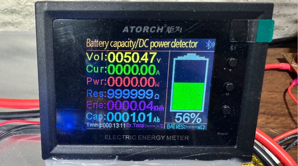
Before making one of these, it's important to consider the practical aspects. In the realm of electronics, especially for hobbyists and DIY enthusiasts, the balance between building a DIY battery pack and purchasing a prebuilt is is important to consider. When it comes to battery level indicators, this decision becomes particularly relevant due to the wide availability and affordability of pre-made options on the market. For example with large home-based battery systems, you can look at several powerwall monitoring options and there is no reason these devices couldn't be used on other batteries.
Cost-Effectiveness: One of the primary reasons to opt for a pre-made battery level indicator is cost. These devices are often available at a fraction of the cost of sourcing individual components like the ESP32, resistors, and LEDs. The economies of scale in manufacturing allow these products to be sold at very competitive prices.
Variety and Features: The market is flooded with a myriad of battery level indicators, each offering different features and specifications. From basic LED displays to more sophisticated ones with LCD or OLED screens, the choices are abundant. This variety allows users to find a product that closely matches their specific needs and preferences.
Time and Effort: Building a battery level indicator from scratch, while educational and fulfilling, requires a significant investment of time and effort. For those who need a quick and efficient solution without the learning curve or the time spent in assembly and troubleshooting, buying a pre-made indicator is a sensible choice.
Conclusion
Creating a simple battery level indicator with an ESP32, a voltage divider, and four LEDs offers a practical and efficient way to monitor battery power levels. By applying the principles of voltage division and leveraging the ESP32's ADC capabilities, users can accurately determine the remaining power in their batteries. The detailed explanation of Ohm's law, along with the step-by-step guide for setting up the voltage divider, makes the process accessible even to beginners.
Also, the provided code simplifies the implementation, allowing enthusiasts and hobbyists to easily build and integrate this indicator into their projects. This project not only serves as a functional tool but also illustrates the versatility and capability of the ESP32 in creating practical electronic devices.


