Table of Contents
What a Spot Welder Really Is
Well, a spot welder is just a massive switch. When I say massive, I mean electrically massive, meaning it can handle thousands of amps for a small period of time. It is a massive fast switch. A switch so electrically massive and so stunningly fast that it makes even the fastest highest-current relays look like child’s playthings.
The type of switching components used in a regulator are called MOSFETs.
So What Is a MOSFET?
A MOSFET is a Metal Oxide Semiconductor Field Effect Transistor. It is driven by voltage at the gate rather than current—although it does technically take some amount of current to drive the gate. It’s an extremely small amount of current, so you can basically consider a MOSFET a voltage-driven device.
A MOSFET is a three-pin device. It has a gate, a drain, and a source. When you have a voltage on the gate relative to the source, then current can flow from drain to source. If you don’t have that voltage at the gate, then no current can flow in that direction.
Current can always flow a little bit in the other direction, but because we are going to have a power supply on one end of the MOSFET and a weld target on the other, the weld target itself will not be supplying any energy to the system. Therefore, it itself will be at zero volts relative to the power supply on the other side of the MOSFET, meaning we only have to care about current flowing in one particular direction.
So that’s the switch part of the welder. It’s the most important part. It’s the one that does all the work.
Gate Voltage, On/Off Behavior, and Why Speed Matters
But it has to be controlled by something. See, you can’t just give a MOSFET any voltage. You have to give it the specific voltage that it needs to work in optimal conditions.
To get the lowest possible resistance for most MOSFETs, you have to give them a gate voltage that’s about 10 volts higher than whatever the source is. So if you connect the source to ground, and then drain goes to your load, then you just need the gate pin to be at about 10 volts.
Now the thing is, if you apply 10 volts to something, it might seem like it gets that voltage instantly. And when you remove the 10 volts, it might seem like it goes away instantly. But there is actually a curve. Instead of it rising straight up or falling straight down on a graph, it’s actually at an angle. In fact, it's somewhat of a slope. It’s called the rise and fall time, and it takes some time for it to get in that position.
Now if you’re just turning on a light or a fan or running some motor or whatever, then you know, you can just apply that gate voltage at a normal speed—like when you press a button or turn a switch, or when a microcontroller powers it on with its GPIO pin—and it’ll work just fine. And then you remove the voltage from the gate using whatever means you use to apply the voltage, and the load turns off. Everything will work as expected.
But if you’re doing thousands of amps—which is the case when we’re making a spot welder—you have to be able to turn that MOSFET on and off very fast. Not just on fast, but off very fast. You have to be able to pull the gate voltage up from 0 to 10 extremely quickly, and you have to be able to shut it down just as fast.
That’s because when transistors are operating in what’s called their linear region, they’re least efficient. So when they’re not completely off or not completely on—when the gate voltage is somewhere under 10 volts but above 0 volts—it will work and current will flow, but the resistance is higher.
Like I said earlier, to get the lowest possible resistance in the MOSFET, you have to have the gate voltage (usually it depends on the MOSFET, but usually) about 10 volts above the source voltage. So for the tiny fraction of time that the gate voltage is going from 0 to 10 volts, the load will be powered, so the weld will actually be happening, and there will be a high stress on those MOSFETs.
So we want to minimize (because we cannot totally eliminate) that rise and fall time as much as possible.
Why You Need a Gate Driver
That’s why we have to use a gate driver to drive this MOSFET. So we will actually send a control signal to the gate driver, and the gate driver will handle communicating with the MOSFET.
The gate driver is able to source and sink a large amount of current. Whereas if you were just to attach a high-current power source, it would be able to source a high amount of current, but it wouldn’t be able to sink a high amount of current. Meaning you could raise the voltage to 10 volts very quickly, but you couldn’t lower it very quickly. It would have to naturally fall, giving the system the opportunity to run during the linear region—and we don’t want that.
So that’s why we need a gate driver that you can just give it either no signal or 5 volts—so basically ground or 5 volts— and it will launch the gate voltage up to whatever voltage you give it at the input of the gate driver. And then whenever you remove that signal, it will clamp down with just as much force to quickly shut off those MOSFETs.
So far we’ve covered the switch itself, which connects the welding circuit, and we’ve covered the gate driver, which is required to properly control the switch.
The Microcontroller: The Coordination Center
Now we have to cover the thing that’s used to control the gate driver, which is a microcontroller. You can use any microcontroller for this. It just has to be able to toggle an I/O pin on and off, and it doesn’t even have to be that fast.
For a low-power weld pulse, it’ll be, you know, 3 to 5 milliseconds. For a very high-power weld pulse, it would be like 60 to 80 milliseconds, maybe 100 milliseconds in some conditions. That’s an extremely high amount of power.
Of course the amount of power that’s transferred depends on much more than just time. I’m just saying: on a scale from zero to max, you’re pretty much dealing with 3 to 5 milliseconds on the low end and 80 to 100 milliseconds on the high end, with the average weld being 20 to 40 milliseconds in duration depending on the material.
Inputs and a Simple User Interface
You have to have a button that is connected to the microcontroller. It could be a foot pedal as well. And when you press that button, the microcontroller looks at the input, sees that the button is pressed, at which point it fires a weld pulse based on the set power level.
The set power level could be set through many ways, but for simplicity and a decent user interface, you could just use a rotary encoder. So you have one pin for the button and two pins for the rotary encoder. Both the button and the rotary encoder need a ground, and that’s all the input you need.
You need some sort of output to let you know what the weld power is set to. So you can attach a small I2C screen, or even an LED strip, and light up a certain amount of LEDs depending on the power level you have the welder set to.
So the microcontroller is the communication center and the coordination center of the entire operation. It listens for the inputs and provides status outputs as far as how much power it’s set to, and etc.
When a weld is triggered, it sends a very tiny voltage for a short amount of time to a gate driver, which is connected to a power supply and has the proper bypass capacitors installed, so it has a nice little current buffer of its own.
And it powers the MOSFET gate, which then switches the weld current through the workpiece.
Powering the Gate: Isolated DC-DC Approach
There are several ways that the gate can be powered, but I recommend getting one of these compact all-in-one isolated DC-to-DC converters. They have several different versions, but for the one I used, you can put 5 volts and ground on the input and you get a totally isolated 15 volt output.
The independent isolated ground on the output is can to the MOSFET source and the power output goes to the gate (of course with the appropriate resistors in between). So that way you can have one 5-volt power supply that powers not only the logic for everything, but it also powers the gate of the MOSFET properly without having to have multiple power supplies.
The Hard Part: Building the Weld Current Path
The difficult part is creating the current path for the weld current to flow through. You can’t just wire up these MOSFETs with small wires or on a very simple board. You have to have very thick traces—very fat pieces of copper or aluminum or nickel or something.
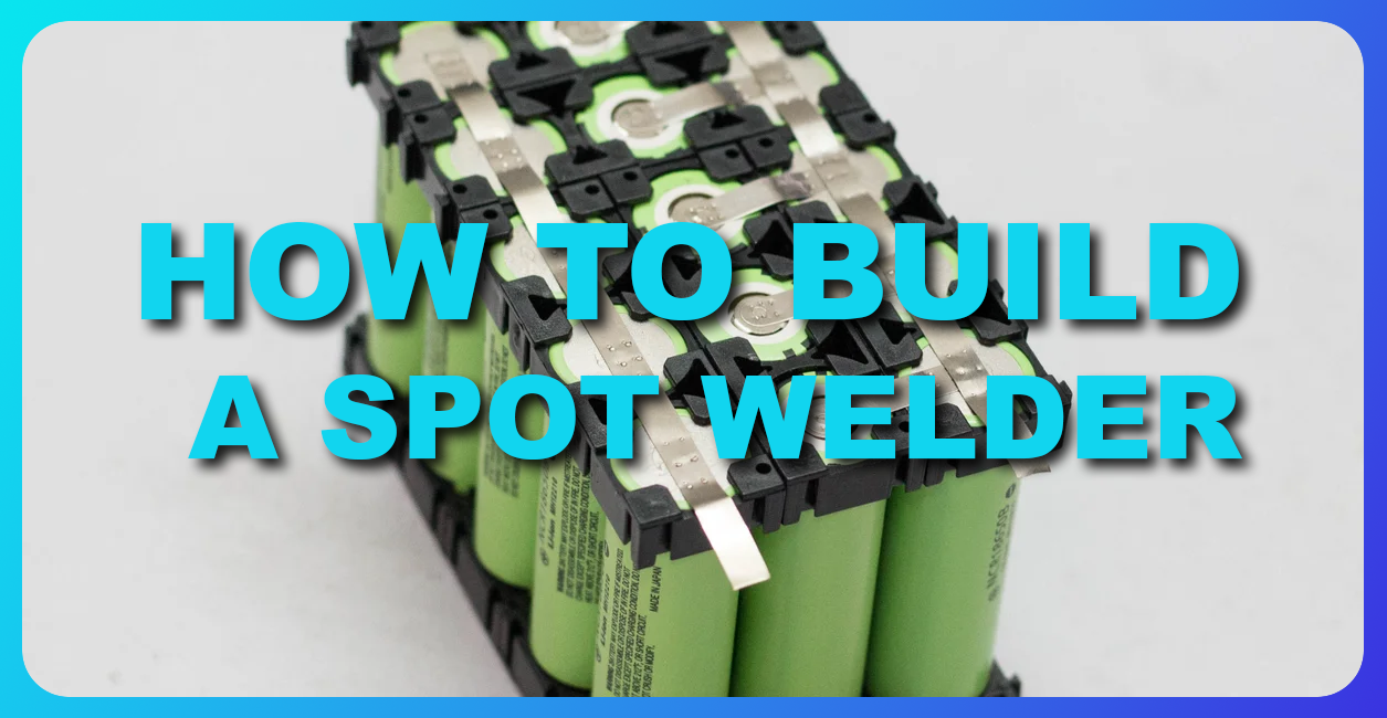
That’s why when you take apart a spot welder you’ll see that there are these massive plates on the board, and they’re there to provide reinforcement for the absolutely massive amount of current.
Because if you have a high resistance path, it doesn’t matter how powerful your system is.
The Power Supply: Batteries vs Capacitor Bank
And by the way, that covers everything but the input power supply for the welder I described. I described the machinery and the mechanism of delivering power from a power source into the weld, but I didn’t cover the power supply itself.
This could be lithium-ion batteries, but it would have to be several large lithium-ion cells, and those cells are going to be put under a tremendous amount of current, so it’s probably not going to last too long.
The best thing you can do is get a capacitor bank. Capacitors, unlike battery cells, store their energy directly in an electric field instead of storing them in a reversible chemical reaction. So the equivalent series resistance of capacitors is just tremendously lower, and their lifespan is tremendously longer.
In a future article I will actually be doing all of this stuff and I will be explaining the process and showing pictures and all of that. But for now, this is just a general information write-up.
Wrap-Up
That’s literally all you need to make a spot welder from scratch. And the architecture—the structure—really is that simple. In a future article related to this topic, I will cover the next steps to actually build something that can weld batteries. Thanks for reading!
Turn the guide into a real build plan
If this article is part of an actual battery, powerwall, or pack-design project, the next step is usually moving from theory into the calculators and planning tools.