Table of Contents
A shunt mod is essentially a way to trick the controller into thinking less current is flowing than actually is flowing. And this, of course, will allow the controller to deliver more current than it was intended to. The overwhelming majority of controllers, inverters, power supplies, and etc., aren't actually measuring current directly. Instead, what they're really doing is they're measuring a very tiny voltage drop that exists across a current shunt.
A current shunt is basically a very precise low-value resistor that produces a given amount of millivolts of voltage drop per amp of flowing current. So, when you do a shunt mod, which essentially lowers the resistance of the shunt, it will make the same amount of current produce less voltage drop. The controller can't see the current directly. It can only see the voltage drop. So, it thinks less current is flowing and it allows more current to flow.
Conductors and Their Properties
Copper traces, wires, shunts, and even battery tabs all have some resistance. If you push current through them, you get:
- A voltage drop (V = I × R), and
- Heat (P = I² × R or P = V × I).
Make something longer or thinner, the resistance goes up. Make it shorter or thicker, the resistance goes down. Change the material and it changes again. Shunt resistors are made so that this resistance is controlled and predictable.
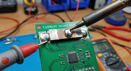
Current Shunts
The case is no different for a current shunt. There is some sort of microcontroller chip in there that monitors the voltage difference across the shunt. If we have a very large current shunt rated for 50 amps continuous, it might produce a voltage drop of around 50 millivolts at that current. That comes out to about 2.5 watts of waste heat (0.05 V × 50 A = 2.5 W), which is no big deal for a reasonably sized current shunt. It will just get a little warm.
That results in a resistance of 1 milliohm (0.001 ohms), because:
- R = V ÷ I = 0.050 ÷ 50 = 0.001 ohms.
The only way your controller knows if you are at 25 amps is if it sees a 25 millivolt voltage drop across that shunt. Double the current, double the millivolts. It’s a straight, linear relationship as long as the shunt is in its normal operating range and not glowing.
Why Controllers Use Shunts Instead of Direct Current Measurement
Most controllers are not using fancy “direct” current sensors. They use shunts because:
- Shunts are cheap. A bit of metal with a known resistance costs much less than a dedicated sensor IC or Hall-effect sensor.
- Shunts are simple. Put it in series, measure the tiny voltage, do some math in the microcontroller.
- They are accurate enough. If you design a 50-amp controller and you can measure current within a few percent, that is good enough for limiting and protection.
So the controller is basically doing this in its head (well, in code):
- Current = (Measured shunt voltage) ÷ (Known shunt resistance).
If you secretly change the shunt resistance but the firmware still thinks it’s the old value, the math is wrong and that’s where the “trick” comes from.
Modifying the Shunt (Shunt Mods)
If you change the characteristics of that shunt, you can change what the controller thinks the current is.
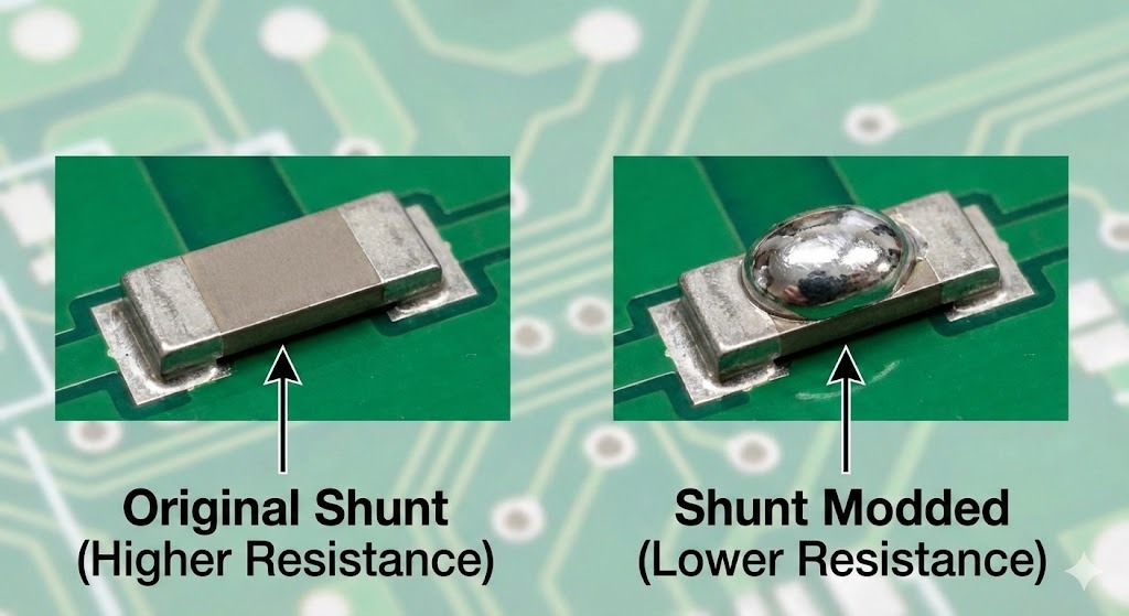
Shunt mods work like this: you put a blob of solder somewhere on the current shunt. Some people run a bead of solder all the way down the current shunt. You do not have to cover the entire thing because every millimeter of that current shunt has a characteristic voltage drop that contributes to the total.
If you decrease the resistance of the current shunt by soldering or welding something to it, it does not really matter where you put it. You are going to lower the overall resistance and perform some amount of current detection deception. Obviously, you would want to completely cover it if you are trying to get the most power out of the situation, but most of the time people are doing a 10 or 20 percent shunt mod.
Example of a Shunt Mod Effect
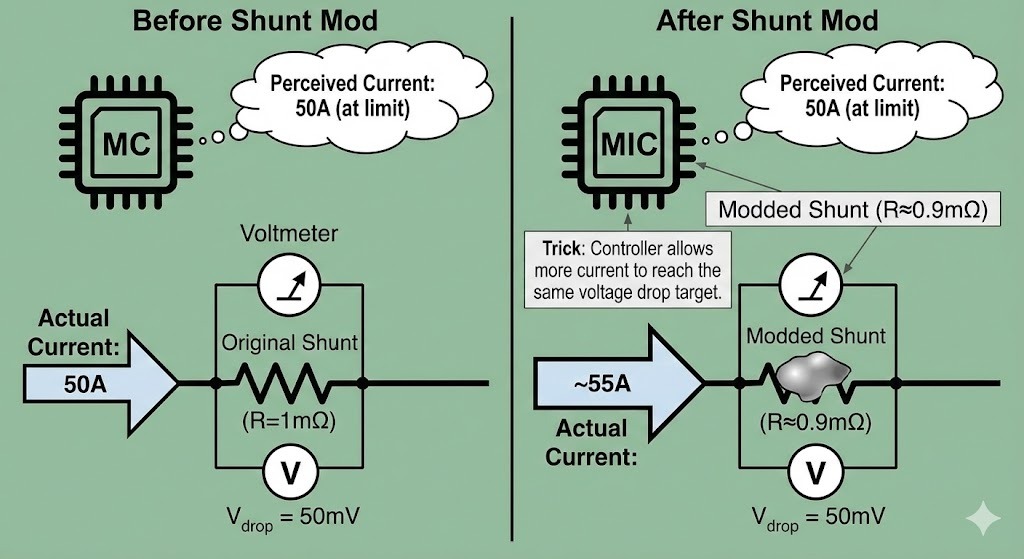
In a normal shunt, you might see 50 millivolts dropped for 50 amps.
If you decrease the resistance of that shunt by 10 percent, you will lower the voltage drop by 10 percent. So when you are running 50 amps, instead of the shunt reporting 50 millivolts to the controller chip, it will report 45 millivolts.
This allows the controller chip to increase the current even more until it again sees 50 millivolts. However, this is no longer 50 amps, it is now about 55 amps. You have effectively raised the current limit, without the controller knowing it, by tampering with the shunt.
How to Estimate the New Current Limit After a Shunt Mod
You can think of this like a simple percentage game. Start with the shunt at its original resistance, and then imagine you reduce that resistance by some amount—for example, a 10% shunt mod means the shunt now has only 90% of its original resistance. The controller keeps turning up the current until the tiny voltage it sees across the shunt reaches the built-in limit it was programmed for. Before the mod, that limit was reached at some “original current.” After the mod, the controller is still aiming for that same voltage reading, but because the shunt now has less resistance, it takes more current to reach that same voltage.
When you do the math, a 10% drop in shunt resistance gives you roughly 11% more current than before, and a 20% drop in shunt resistance gives you about 25% more current. That’s how a small change in shunt resistance turns into a noticeable bump in current.
What Actually Changes When You Do a Shunt Mod
When you do a shunt mod, the funny thing is that, from the controller’s point of view, nothing has really changed. It still believes, “When the shunt hits 50 millivolts, I’m at my limit,” because that’s what it was programmed to look for. But in reality, the shunt now produces fewer millivolts for each amp of current than it did before. That means you have to push more current through it to reach the same tiny voltage the controller is watching.
As a result, everything downstream is now working harder: the MOSFETs, any diodes in the path, the copper traces on the circuit board, the connectors, and even the battery, wiring, and motor. All of those parts are now seeing more current than the designer originally intended, even though the controller still thinks it’s right at its normal limit.
Heat and Ohmic Losses For Shunt Mods
One of the big side effects of a shunt mod is extra heat everywhere in the power path. Power loss in a resistor is I²R. Notice that current is squared.
If you increase the current by 10 percent, the power loss in anything resistive goes up like this:
- P_new = (1.1 × I)² × R = 1.21 × I² × R.
That is a 21 percent increase in heat for only 10 percent more current.
So if your MOSFETs, traces, or connectors were already getting warm, they will get noticeably hotter. A controller might have been happy at 50 amps but very unhappy at 60 amps, and it won’t tell you that until it releases the magic smoke.
Limits and Dangers of Shunt Mods
Shunt mods are not free power. You are stealing the margin that the designer put in for safety and reliability. Some things to keep in mind:
- MOSFET limits
The transistors inside have a max current rating and a max temperature. They might be okay at the factory current but pushed over the edge by your new limit, especially in hot weather or with poor airflow. - PCB trace and bus bar limits
The copper inside the controller also has a resistance and a current rating. Too much current and it can discolor, delaminate, or literally burn open in extreme cases. - Connectors and wiring
Connectors have contact resistance. A little extra current can make a connector go from “warm” to “melted plastic” surprisingly fast if it was marginal to start with. - Battery stress
Your battery now sees higher discharge current. That means more voltage sag, more heating, and reduced cycle life. In bad cases it can trigger BMS shutdown, swelling, or worse. - No firmware awareness
The firmware still thinks everything is within spec. It will not warn you that you’re running parts beyond what they were designed for.
If you go too far with a shunt mod, you can very easily blow the controller or create a fire hazard, especially on high-power systems.
Why People Only Do 10–20 Percent Shunt Mods
Most of the time people are doing a 10 or 20 percent shunt mod because:
- It gives a noticeable bump in performance.
- It doesn’t instantly kill everything in many designs.
- It stays roughly within whatever margin the manufacturer left, instead of obliterating it.
That does not mean it is safe in every controller. It just means that small changes are less likely to immediately destroy things than doubling the current.
If you cut the resistance in half (50 percent mod), you are asking for about double the current at the same sense voltage. That is a huge increase in stress:
- Current ≈ 2×
- I²R losses ≈ 4×
That sort of jump is where things tend to fail very suddenly.
Why the Location of the Solder Doesn’t Matter
As long as you are soldering across the same shunt element (or adding a parallel path across it), you are lowering the total resistance.
- You can think of the shunt as a piece of resistor metal with R spread evenly along its length.
- Adding solder anywhere along that length is like putting a lower-resistance “shortcut” in parallel with part of it.
- The total effective resistance drops.
You don’t need to perfectly coat the whole thing to change its characteristics. However, completely bridging the shunt or replacing it with a thick copper bar would basically remove the current limiting altogether, which is normally a very bad idea.
Why Manufacturers Don’t Just Ship It “Shunt Modded”
If it is this easy to get more power, why don’t manufacturers just ship the controller with a smaller shunt value from the factory? A few reasons:
- Reliability and warranty
They need the product to survive all sorts of users, environments, and loads. If they push everything to the edge, returns and failures go up. - Thermal design
The heatsink, case, and cooling are designed for a certain amount of heat. More current means more heat everywhere. - Component cost
To safely handle more current, they might need more expensive MOSFETs, thicker copper, better connectors, etc. - Product segmentation
Sometimes the same hardware is used in multiple models. The “premium” version might just have different firmware or a different shunt, and you are essentially hacking your way into that higher tier.
Conclusion
Current shunt mods work by decreasing the resistance of the current shunt, which lowers the voltage drop under a particular amount of current. This skews the results that the controller chip sees, allowing it to operate higher than normal. The controller chip believes it has hit its maximum of 50 amps, but because of the altered shunt, it is actually running at a higher current — an intentionally false measurement.
By understanding that the controller only sees millivolts across a very low-value resistor, you can see why changing that resistor’s value changes everything. You get more current and more power, but you also get more heat, more stress, and less safety margin. How far you push it determines whether you get a bit more performance or a blown controller.
Turn the guide into a real build plan
If this article is part of an actual battery, powerwall, or pack-design project, the next step is usually moving from theory into the calculators and planning tools.